Privacy statement: Your privacy is very important to Us. Our company promises not to disclose your personal information to any external company with out your explicit permission.
model numarası.: NSO4GU3AB
Ulaşım: Ocean,Air,Express,Land
Ödeme şekli: L/C,T/T,D/A
Incoterm: FOB,EXW,CIF
4GB 1600MHz 240 pimli DDR3 UDIMM
Revizyon Geçmişi
|
Revision No. |
History |
Draft Date |
Remark |
|
1.0 |
Initial Release |
Apr. 2022 |
|
![]()
Sipariş Bilgi Tablosu
|
Model |
Density |
Speed |
Organization |
Component Composition |
|
NS04GU3AB |
4GB |
1600MHz |
512Mx64bit |
DDR3 256Mx8 *16 |
Tanım
Hengstar, DDR3 SDRAM DIMM'leri (SFFFEF'siz Çift Veri Hızı Senkron DRAM çift sıralı bellek modülleri), DDR3 SDRAM cihazlarını kullanan düşük güç, yüksek hızlı çalışma bellek modülleridir. NS04Gu3AB, on altı 256m x 8 bit FBGA bileşenlerine dayanan 512m x 64 bit iki rütbe 4GB DDR3-1600 CL11 1.5V SDRAM gereksiz DIMM ürünüdür. SPD, 1.5V'de 11-11-11'lik JEDEC Standart Gecikme DDR3-1600 zamanlamasına programlanmıştır. Her 240 pimli DIMM altın temas parmakları kullanır. SDRAM, PC'ler ve iş istasyonları gibi sistemlere yüklendiğinde ana bellek olarak kullanılmak üzere tasarlanmıştır.
Özellikler
Power Tedarik: VDD = 1.5V (1.425V - 1.575V)
VDDQ = 1.5V (1.425V ila 1.575V)
1600MB/sn/pim için 800MHz FCK
8 Bağımsız İç Banka
Programlanabilir CAS gecikmesi: 11, 10, 9, 8, 7, 6
Programlanabilir Katkı Gecikmesi: 0, CL - 2 veya CL - 1 Saat
8-bit ön getirme
Püret uzunluğu: 8 (herhangi bir sınırsız, sadece “000” başlangıç adresi ile sıralı), 4 TCCD = 4 ile kesintisiz okumaya veya yazmaya izin vermeyen [ya A12 veya MRS kullanarak anında]
BI-yönlü diferansiyel veri flaşı
Dürüst (benlik) kalibrasyon; ZQ PIN ile dahili kendi kendine kalibrasyon (RZQ: 240 ohm ±%1)
ODT pimi kullanarak ölüme sonlandırma
Orta Yenileme Dönemi 7.8us 85 ° C'den daha düşük bir sürede, 85 ° C'de 3.9us <TCE <95 ° C
Senkron sıfırlama
Tartışılabilir veri-çıktı sürücü mukavemeti
Baskı topolojisi
PCB: Yükseklik 1.18 ”(30mm)
ROHS uyumlu ve halojensiz
Anahtar zamanlama parametreleri
|
MT/s |
tRCD(ns) |
tRP(ns) |
tRC(ns) |
CL-tRCD-tRP |
|
DDR3-1600 |
13.125 |
13.125 |
48.125 |
2011/11/11 |
Adres tablosu
|
Configuration |
Refresh count |
Row address |
Device bank address |
Device configuration |
Column Address |
Module rank address |
|
4GB |
8K |
32K A[14:0] |
8 BA[2:0] |
2Gb (256 Meg x 8) |
1K A[9:0] |
2 S#[1:0] |
PIN Açıklamaları
|
Symbol |
Type |
Description |
|
Ax |
Input |
Address inputs: Provide the row address for ACTIVE commands, and the column |
|
BAx |
Input |
Bank address inputs: Define the device bank to which an ACTIVE, READ, WRITE, or |
|
CKx, |
Input |
Clock: Differential clock inputs. All control, command, and address input signals are |
|
CKEx |
Input |
Clock enable: Enables (registered HIGH) and disables (registered LOW) internal circuitry |
|
DMx |
Input |
Data mask (x8 devices only): DM is an input mask signal for write data. Input data is |
|
ODTx |
Input |
On-die termination: Enables (registered HIGH) and disables (registered LOW) |
|
Par_In |
Input |
Parity input: Parity bit for Ax, RAS#, CAS#, and WE#. |
|
RAS#, |
Input |
Command inputs: RAS#, CAS#, and WE# (along with S#) define the command being |
|
RESET# |
Input |
Reset: RESET# is an active LOW asychronous input that is connected to each DRAM and |
|
Sx# |
Input |
Chip select: Enables (registered LOW) and disables (registered HIGH) the command |
|
SAx |
Input |
Serial address inputs: Used to configure the temperature sensor/SPD EEPROM address |
|
SCL |
Input |
Serial |
|
CBx |
I/O |
Check bits: Used for system error detection and correction. |
|
DQx |
I/O |
Data input/output: Bidirectional data bus. |
|
DQSx, |
I/O |
Data strobe: Differential data strobes. Output with read data; edge-aligned with read data; |
|
SDA |
I/O |
Serial |
|
TDQSx, |
Output |
Redundant data strobe (x8 devices only): TDQS is enabled/disabled via the LOAD |
|
Err_Out# |
Output (open |
Parity error output: Parity error found on the command and address bus. |
|
EVENT# |
Output (open |
Temperature event: The EVENT# pin is asserted by the temperature sensor when critical |
|
VDD |
Supply |
Power supply: 1.35V (1.283–1.45V) backward-compatible to 1.5V (1.425–1.575V). The |
|
VDDSPD |
Supply |
Temperature sensor/SPD EEPROM power supply: 3.0–3.6V. |
|
VREFCA |
Supply |
Reference voltage: Control, command, and address VDD/2. |
|
VREFDQ |
Supply |
Reference voltage: DQ, DM VDD/2. |
|
VSS |
Supply |
Ground. |
|
VTT |
Supply |
Termination voltage: Used for control, command, and address VDD/2. |
|
NC |
– |
No connect: These pins are not connected on the module. |
|
NF |
– |
No function: These pins are connected within the module, but provide no functionality. |
Notlar : Aşağıdaki PIN Açıklama tablosu, tüm DDR3 modülleri için tüm olası pimlerin kapsamlı bir listesidir. Listelenen tüm pimler Bu modülde desteklenmez. Bu modüle özgü bilgiler için PIN atamalarına bakın.
Fonksiyonel blok diyagramı
4GB, 512MX64 Modülü (x8'in 2rantı)


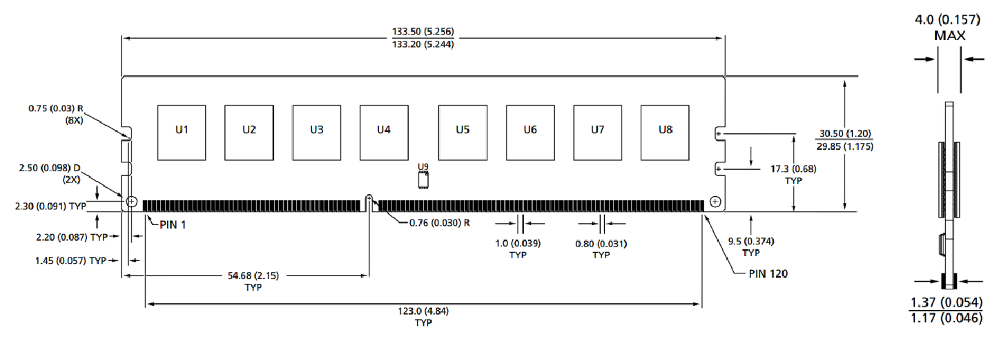
Modül boyutları
Önden görünüş

Önden görünüş

Notlar:
1. Tüm boyutlar milimetre (inç); Maks/dk veya tipik (tip) belirtildi.
2. Aksi belirtilmedikçe tüm boyutlarda ± 0.15mm.
3. Boyutsal diyagram sadece referans içindir.
Ürün kategorileri : Endüstriyel Akıllı Modül Aksesuarları


Privacy statement: Your privacy is very important to Us. Our company promises not to disclose your personal information to any external company with out your explicit permission.

Fill in more information so that we can get in touch with you faster
Privacy statement: Your privacy is very important to Us. Our company promises not to disclose your personal information to any external company with out your explicit permission.